Verfasst vom Ingenieurteam bei TOKO TECH. TOKO TECH ist ein exportorientiertes Produktionsunternehmen, das sich auf die Forschung und Entwicklung, die Produktion und den Vertrieb von hochwertigen Metallrohrleitungssystemen spezialisiert hat. Unser Hauptsitz befindet sich in Shanghai, China, mit modernen Produktionsanlagen im Yangtze-Flussdelta. Wir halten uns an die Kernphilosophie "Qualität an erster Stelle, Innovation im Vordergrund". Unser Ziel ist es, hochleistungsfähige, korrosionsbeständige und Hochtemperatur-/Hochdruck-Rohrleitungsprodukte für globale Kunden aus den Bereichen Petrochemie, Energie und Kraftwerke, Schiffbau, Pharmazeutik und Lebensmittelverarbeitung sowie Umwelttechnik zu liefern.
In den hochpräzisen Bereichen der industriellen Thermodynamik und der Strömungstechnik ist das Gleichgewicht zwischen thermischer Effizienz und Investitionsaufwand eine ständige Herausforderung. Facility Manager, Maschinenbauingenieure und Beschaffungsspezialisten müssen sich in einem Labyrinth thermodynamischer Prinzipien zurechtfinden, um Systeme zu entwerfen, die sowohl effektiv als auch wirtschaftlich tragfähig sind. Unter diesen Prinzipien sticht die 10-13-Regel für Wärmetauscher als wichtiger Maßstab hervor. Das Verständnis und die Anwendung dieser Regel sind entscheidend für die Optimierung des Anlagenbetriebs, die Minimierung der Energieverschwendung und die Verlängerung des Lebenszyklus Ihrer Pipeline-Infrastruktur.
Aus unserer Erfahrung als Lieferant von hochwertigen Metallrohrleitungssystemen für die weltweite Petrochemie und Energieerzeugung wissen wir aus erster Hand, zu welchen Betriebsausfällen es kommt, wenn grundlegende thermodynamische Regeln ignoriert werden. Ein Wärmetauscher ist nur so effektiv wie seine Konstruktionsparameter und die metallurgische Qualität seiner inneren Komponenten. In diesem umfassenden technischen Leitfaden gehen wir auf die genaue Definition der 10-13-Regel für Wärmetauscher ein, analysieren ihre wirtschaftlichen und betrieblichen Auswirkungen und erläutern, wie die Auswahl der richtigen Werkstoffe dafür sorgen kann, dass Ihre Systeme jahrzehntelang mit höchster Effizienz arbeiten.
Inhaltsübersicht
- 1. Verstehen der 10-13-Regel für Wärmetauscher
- 2. Thermodynamik vs. Ökonomie: Die CapEx- und OpEx-Bilanz
- 3. Die Rolle der logarithmischen mittleren Temperaturdifferenz (LMTD)
- 4. Materialauswahl: Langfristige Einhaltung der Vorschrift
- 5. Der Einfluss von Fouling auf die 10-13-Regel für Wärmetauscher
- 6. Wie TOKO TECH die Optimierung von Wärmetauschern unterstützt
- 7. Zusammenfassende Tabelle: Anwendung der 10-13-Regel für Wärmetauscher
- 8. Häufig gestellte Fragen (FAQs)
- 9. Akademische und industrielle Referenzen
1. Verstehen der 10-13-Regel für Wärmetauscher
Um die 10-13-Regel für Wärmetauscher zu verstehen, muss man zunächst das Konzept der "Annäherungstemperatur" verstehen. Bei jedem Wärmeübertragungsprozess ist die Annäherungstemperatur der Unterschied zwischen der Temperatur der den Wärmetauscher verlassenden Flüssigkeit und der Temperatur des in den Wärmetauscher eintretenden Heiz- oder Kühlmediums. Bei einer Kühlanwendung ist dies zum Beispiel die Temperaturdifferenz zwischen der heißen Flüssigkeit, die das Gerät verlässt, und dem kalten Wasser, das in das Gerät eintritt.
Die 10-13-Regel für Wärmetauscher besagt, dass diese Vorlauftemperatur idealerweise zwischen 10 Grad und 13 Grad Fahrenheit (etwa 5,5 bis 7,2 Grad Celsius) liegen sollte. Wir empfehlen dieses spezifische Temperaturfenster, weil es die optimale Schnittmenge zwischen thermischer Effizienz und der physischen Größe des Wärmetauschers darstellt.
Wenn Sie ein System entwerfen, bei dem die Vorlauftemperatur unter 10 Grad Fahrenheit gedrückt wird, wird die treibende Kraft für die Wärmeübertragung so gering, dass die erforderliche Oberfläche des Wärmetauschers gegen unendlich geht. Lässt man dagegen zu, dass die Vorlauftemperatur 13 Grad Celsius übersteigt, wird das System höchst ineffizient, verschwendet große Mengen an thermodynamischem Potenzial und erhöht die Energiebelastung für sekundäre Kühl- oder Heizsysteme. Daher ist die Einhaltung der 10-13-Regel für Wärmetauscher der Industriestandard, um ein harmonisches Gleichgewicht in der Verfahrenstechnik zu erreichen.
2. Thermodynamik vs. Ökonomie: Die CapEx- und OpEx-Bilanz
Nach unserer Erfahrung im Energie- und Kraftwerkssektor wird die Entscheidung, die 10-13-Regel für Wärmetauscher strikt einzuhalten, gleichermaßen von wirtschaftlichen und physikalischen Erwägungen bestimmt. Die Planung von Industrieanlagen erfordert eine sorgfältige Abwägung zwischen Kapitalaufwand (CapEx) und Betriebsaufwand (OpEx).
Wenn ein Ingenieur versucht, die 10-13-Regel für Wärmetauscher zu verletzen, indem er ein System mit einer 5-Grad-Annäherungstemperatur entwirft, muss die physische Grundfläche der Ausrüstung dramatisch zunehmen. Das bedeutet, dass exponentiell mehr interne Rohre gekauft werden müssen. Während dies theoretisch einen Bruchteil der Energie einsparen könnte (OpEx), sind die anfänglichen Investitionskosten, die für den Kauf von kilometerlangen zusätzlichen Rohren erforderlich sind, finanziell nicht zu rechtfertigen. Die schiere Größe der Anlage bringt auch strukturelle Herausforderungen mit sich, die robustere Fundamente und größere Edelstahl-Rohrverbindungen erfordern, um das erhöhte Flüssigkeitsvolumen und Gewicht zu bewältigen.
Andererseits kann man einen sehr kleinen, billigen Wärmetauscher bauen, wenn man die 10-13-Regel für Wärmetauscher ignoriert und für eine 20-Grad-Annäherungstemperatur auslegt. Allerdings werden die Betriebskosten in die Höhe schnellen, weil das System nicht genug Wärme entziehen kann, so dass die Kältemaschinen oder Heizkessel gezwungen sind, mehr zu arbeiten. Indem Sie das 10-13-Grad-Fenster anpeilen, optimieren Sie die Investitionsrendite über den Lebenszyklus der Anlage.
3. Die Rolle der logarithmischen mittleren Temperaturdifferenz (LMTD)
Um die 10-13-Regel für Wärmetauscher vollständig zu verstehen, ist es wichtig, die logarithmische mittlere Temperaturdifferenz (LMTD) zu kennen. Die LMTD ist der logarithmische Durchschnitt der Temperaturdifferenz zwischen den heißen und kalten Strömen an beiden Enden des Wärmetauschers. Je größer die LMTD ist, desto mehr Wärme wird über dieselbe Fläche übertragen.
Die insgesamt erforderliche Wärmeübertragungsfläche ist umgekehrt proportional zur LMTD. Wenn man die Annäherungstemperatur unter die durch die 10-13-Regel für Wärmetauscher definierte Schwelle drückt, fällt die LMTD sprunghaft ab. Wenn sich die LMTD dem Wert Null nähert, wächst die erforderliche Fläche exponentiell. Ingenieure verwenden die 10-13-Regel für Wärmetauscher als Schutzmaßnahme, um sicherzustellen, dass die LMTD hoch genug bleibt, um eine effiziente Wärmeübertragung durch die Metallwände der Rohre zu gewährleisten, ohne dass ein übermäßig großes Rohrbündel erforderlich ist.
4. Materialauswahl: Langfristige Einhaltung der Vorschrift
Ein System zu entwerfen, das die 10-13-Regel für Wärmetauscher auf dem Papier erfüllt, ist nur der erste Schritt. Die eigentliche Herausforderung besteht darin, diese Effizienz über Jahre hinweg im Dauerbetrieb in rauen Umgebungen wie petrochemischen Anlagen und pharmazeutischen Verarbeitungseinrichtungen aufrechtzuerhalten. Die Wärmeleitfähigkeit, die Wandstärke und die Korrosionsbeständigkeit Ihrer Rohrleitungsprodukte wirken sich direkt auf die Fähigkeit aus, die vorgesehene Ansaugtemperatur zu halten.
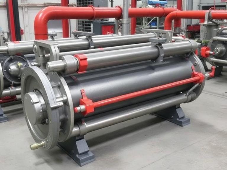
Wir empfehlen die Verwendung von hochwertigen Nahtlose Rohre/Rohre für kritische Wärmetauscheranwendungen. Nahtlose Rohre haben keine Längsschweißnaht, was für eine hervorragende strukturelle Integrität unter hohem Druck sorgt und eine perfekt gleichmäßige Wandstärke für eine konstante Wärmeleitfähigkeit gewährleistet. Wenn Standard-Kohlenstoffstahl für hochkorrosive oder extreme Temperaturumgebungen nicht ausreicht, bietet TOKO TECH spezielle Lösungen an.
Unsere nahtlosen Rohre aus Nickellegierungen und unsere Stangen aus Nickellegierungen sind speziell für diese anspruchsvollen Bedingungen entwickelt worden. Nickellegierungen bieten eine außergewöhnliche Beständigkeit gegen Lochfraß, Spaltkorrosion und Spannungsrisskorrosion. Wenn ein Wärmetauscherrohr korrodiert oder sich verschlechtert, sinkt seine Wärmeleitfähigkeit, was sofort dazu führt, dass das System die 10-13-Regel für Wärmetauscher nicht mehr erfüllt. Durch die Investition in hochwertige metallurgische Produkte stellen Sie sicher, dass die thermodynamische Leistung Ihrer Anlage über Jahrzehnte hinweg den ursprünglichen technischen Spezifikationen entspricht.
5. Der Einfluss von Fouling auf die 10-13-Regel für Wärmetauscher
Unter Fouling versteht man die Ansammlung von unerwünschtem Material auf den festen Oberflächen des Wärmetauschers, das die Wärmeübertragung stark behindert. Im Laufe der Zeit bildet sich durch biologisches Wachstum, chemische Ablagerungen oder Partikelablagerungen eine isolierende Schicht auf der Innen- oder Außenseite der Rohre. Unserer Erfahrung nach ist Fouling der Hauptgrund dafür, dass in Betrieb befindliche Wärmetauscher langsam die 10-13-Regel für Wärmetauscher nicht mehr einhalten.
Je dicker die Verschmutzungsschicht wird, desto größer wird der Wärmewiderstand. Um die gleiche Wärmemenge zu übertragen, erhöht sich natürlich die Anströmtemperatur von optimalen 12 Grad auf 15, 18 oder sogar 20 Grad. Um dem entgegenzuwirken, müssen die Ingenieure in der ersten Entwurfsphase eine "Verschmutzungsmarge" einkalkulieren. Darüber hinaus ist die Auswahl ultraglatter interner Oberflächen, wie sie in unseren hochwertigen Geschweißte Rohre/Rohre und Coiled Tubing/Control Line Tube reduziert die Mikroabriebstellen, an denen sich normalerweise Ablagerungen und biologische Stoffe festsetzen. Regelmäßige Wartung, kombiniert mit hochwertigen Metalloberflächen, stellt sicher, dass Ihre Anlage weiterhin streng innerhalb der Parameter der 10-13-Regel für Wärmetauscher arbeitet.
6. Wie TOKO TECH die Optimierung von Wärmetauschern unterstützt
Bei TOKO TECH bedeutet unser Bekenntnis zu "Quality First, Innovation Driven", dass wir mehr tun als nur Rohre zu liefern; wir liefern die grundlegende Architektur für thermische Effizienz. Wenn globale Kunden aus den Bereichen Schiffbau und Umwelttechnik an uns herantreten, um Systeme zu bauen, die die 10-13-Regel für Wärmetauscher einhalten, bieten wir ein ganzheitliches Produktpaket an.
Neben unseren Kernrohren ist die Integrität des gesamten Kreislaufs von entscheidender Bedeutung. Druckabfälle und Strömungsturbulenzen, die durch schlechte Verbindungen verursacht werden, können die für eine optimale Wärmeübertragung erforderliche Fluiddynamik stören. Wir fertigen Präzision Stainless Steel Pipe Fitting Komponenten, die nahtlose, leckagefreie Übergänge zwischen den Rohrleitungen gewährleisten und die erforderlichen Druckgeschwindigkeiten exakt einhalten. Bei hochspezialisierten Instrumenten und chemischen Einspritzsystemen, die diese Wärmetauscher überwachen, machen unsere Endlosrohre (Coiled Tubing/Control Line Tube) mechanische Zwischenfittings überflüssig, wodurch das Risiko von Ausfällen in Hochdruckumgebungen drastisch reduziert wird.
7. Zusammenfassende Tabelle: Anwendung der 10-13-Regel für Wärmetauscher
| Anflugtemperaturbereich | Thermodynamischer Wirkungsgrad | Wirtschaftliche Auswirkungen (CapEx & OpEx) | Operative Empfehlung |
|---|---|---|---|
| Unter 10°F (< 5,5°C) | Extrem hoch | Unvertretbare Investitionskosten (große Fläche erforderlich). Niedrige OpEx. | Vermeiden. Erfordert exponentiell mehr nahtlose Rohre. |
| 10°F bis 13°F (5,5°C bis 7,2°C) | Optimal (Die 10-13-Regel für Wärmetauscher) | Perfektes Gleichgewicht zwischen überschaubaren Investitionsausgaben und effizienten Betriebsausgaben. | Sehr empfehlenswert. Verwenden Sie hochwertige Legierungen, um die Haltbarkeit zu gewährleisten. |
| 14°F bis 19°F (7,7°C bis 10,5°C) | Mäßig bis niedrig | Niedrige CapEx (kleinere Geräte). Hohe OpEx (Energieverschwendung). | Nur für unkritische, wenig beanspruchte Gebrauchskühlung akzeptabel. |
| Über 20°F (> 11,1°C) | Schlecht | Minimale CapEx. Inakzeptable Betriebskosten aufgrund von massivem Energieverlust. | System umgestalten. Die Prozessflüssigkeit wird nicht ausreichend gekühlt/geheizt. |
8. Häufig gestellte Fragen (FAQs)
9. Akademische und industrielle Referenzen
- U.S. Department of Energy (DOE) - Advanced Manufacturing Office: Richtlinien zur Effizienz der industriellen Wärmeübertragung
- National Renewable Energy Laboratory (NREL) - Thermodynamische Optimierung in Stromkreisläufen
- Heat Transfer Research, Inc. (HTRI) - Industrienormen für die Auslegung von Wärmetauschern und Ansatztemperaturen
- Amerikanisches Institut für Chemieingenieure (AIChE) - CapEx- und OpEx-Ausgleich in der Verfahrenstechnik