Auteur TOKO TECH | Global Leaders in High-End Metal Pipeline Systems
In the highly demanding industries of petrochemicals, energy generation, and pharmaceutical processing, the safety and integrity of pressurized equipment cannot be overstated. Among the most critical pieces of equipment in these sectors are heat exchangers. When designing these systems, mechanical and process engineers must account for catastrophic failure scenarios, the most severe being a tube rupture. A frequently referenced standard in mitigating this risk is the 10 13 rule for échangeur de chaleur à calandre et à tube design.
Headquartered in Shanghai, China, with advanced manufacturing facilities in the Yangtze River Delta, TOKO TECH is an export-driven enterprise dedicated to the core philosophy of "La qualité d'abord, l'innovation ensuite. We specialize in providing high-performance, corrosion-resistant, and high-temperature/high-pressure pipeline products for the petrochemical, energy and power, shipbuilding, pharmaceutical, and environmental engineering sectors.
Understanding what the 10 13 rule for shell and tube heat exchanger means is essential for ensuring plant safety while avoiding the unnecessary costs of over-engineering pressure relief systems. From our experience supplying critical materials to global mega-projects, a deep comprehension of the codes governing overpressure scenarios separates standard engineering from world-class system design. In this comprehensive guide, we will break down the mathematics, the relevant American Petroleum Institute (API) and American Society of Mechanical Engineers (ASME) codes, and the material considerations necessary for safely navigating tube rupture scenarios.
Table des matières
- 1. What is the 10 13 Rule for Shell and Tube Heat Exchanger?
- 2. The Engineering Mathematics Behind the 10/13 Ratio
- 3. API 521 and the Corrected Hydrotest Pressure
- 4. Preventing Tube Rupture: The Role of Material Integrity
- 5. Step-by-Step Calculation Example
- 6. Exceptions: When NOT to Use the 10/13 Rule
- 7. Summary Table: Application of the Rule
- 8. Frequently Asked Questions (FAQs)
- 9. Industry References
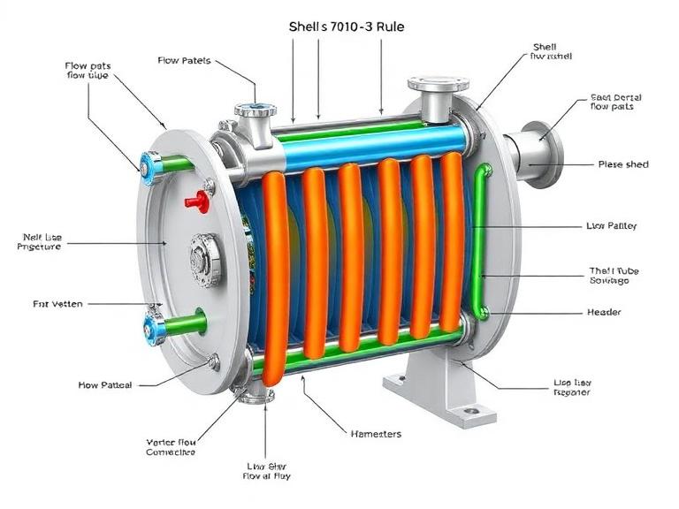
1. What is the 10 13 Rule for Shell and Tube Heat Exchanger?
The 10 13 rule for shell and tube heat exchanger is a specific safety engineering guideline used to determine whether a Pressure Safety Valve (PSV) is required on the low-pressure side of a heat exchanger to protect it against a tube rupture event. In most configurations, the cooling medium flows through the shell side at a lower pressure, while the hot, process fluid flows through the tube side at a much higher pressure.
If a tube were to suddenly rupture, the high-pressure fluid would instantly enter the low-pressure shell side. This rapid ingress of fluid creates an immediate pressure surge. The 10 13 rule dictates that if the corrected design pressure of the low-pressure side is equal to or greater than 10/13ths (approximately 77%) of the design pressure of the high-pressure side, a PSV is not required for the tube rupture scenario.
By applying this rule, engineers can safely omit large, expensive relief valves and the associated flare headers, provided the low-pressure side possesses enough inherent structural integrity to withstand the equalization of pressure.
2. The Engineering Mathematics Behind the 10/13 Ratio
You may wonder, why exactly 10/13? The origin of the 10 13 rule for shell and tube heat exchanger lies within the construction codes, specifically ASME Section VIII, Division 1.
According to this universally accepted pressure vessel code, after a piece of equipment is fabricated, it must undergo a hydrostatic test to verify its mechanical integrity. ASME Section VIII Div 1 mandates that the hydrostatic test pressure must be at least 1.3 times the Maximum Allowable Working Pressure (MAWP) or design pressure of the vessel.
Mathematically, the relationship is expressed as:
Test Pressure = 1.3 × Design Pressure
If we reverse this equation to find the ratio of the design pressure to the test pressure, we get 1 / 1.3, which simplifies exactly to the fraction 10/13.
Therefore, if the low-pressure shell’s design pressure is at least 10/13 of the high-pressure tube’s design pressure, the shell’s mandatory hydrotest pressure (which is 1.3 times its design pressure) will mathematically equal or exceed the maximum possible pressure from the tube side. Because the shell has already been physically tested and proven to hold that pressure without failing, engineers can confidently conclude it will not burst during a tube rupture.
3. API 521 and the Corrected Hydrotest Pressure
While the mathematical premise is simple, its real-world application requires rigorous attention to thermodynamics. API Standard 521 (Pressure-relieving and Depressuring Systems) states that one must use the corrected hydrotest pressure when evaluating the 10 13 rule for shell and tube heat exchanger.
Metals lose tensile and yield strength as temperatures increase. A heat exchanger shell is hydrotested at ambient room temperature, but during operation, it may be exposed to temperatures exceeding 400°C in a petrochemical refinery. To account for this, engineers must apply a temperature correction factor:
Corrected Hydrotest Pressure = 1.3 × MAWP × (Allowable Stress at Operating Temp / Allowable Stress at Test Temp)
From our experience, failing to apply this temperature correction factor is a common, yet highly dangerous pitfall for junior process engineers. If the operating temperature significantly degrades the metal’s yield strength, the corrected hydrotest pressure will drop, and the shell may fail the 10/13 criteria, thereby legally and ethically requiring a PSV.
4. Preventing Tube Rupture: The Role of Material Integrity
While calculating relief scenarios is vital, the ultimate goal of any facility manager is to prevent the tube rupture from occurring in the first place. Tube ruptures are typically caused by flow-induced vibration, thermal fatigue, or severe localized corrosion. At TOKO TECH, we know that superior material selection is the primary defense against these catastrophic failures.
We recommend utilizing our advanced pipeline products to ensure the longevity and safety of your heat transfer equipment. By adhering to our “Quality First, Innovation Driven” philosophy, we provide materials that drastically reduce rupture risks:
- Tube sans soudure: For high-pressure tube bundles, our seamless products offer continuous grain structure and uniform wall thickness, eliminating the weak points commonly associated with weld seams in high-stress applications.
- Tube sans soudure en alliage de nickel: In environments involving highly aggressive chlorides or acidic media (common in pharmaceutical and petrochemical processing), standard stainless steel is susceptible to stress corrosion cracking. Our nickel alloy tubes provide unparalleled resistance, ensuring the pressure boundary remains intact.
- Tubes et tuyaux soudés: For lower-pressure utility applications, our precision-welded tubes offer excellent thermal conductivity and economic efficiency without compromising structural safety.
- Barre/tige en alliage de nickel: The integrity of the tubesheet—the component separating the high and low-pressure sides—is critical. Our high-strength nickel alloy bars are ideal for fabricating robust tubesheets and baffles.
- Raccord de tuyauterie en acier inoxydable: Secure all external nozzles and process connections with our precision-engineered fittings to prevent flange leaks during pressure surges.
- Tubes enroulés/Tubes pour lignes de contrôle: Ensure accurate, real-time pressure monitoring across your exchanger network with our durable control lines, enabling rapid detection of pressure anomalies before a full rupture occurs.
5. Step-by-Step Calculation Example
To fully grasp the 10 13 rule for shell and tube heat exchanger, let us look at a practical scenario evaluated by an engineering team.
System Parameters:
- Tube Side (High Pressure) Design Pressure: 50 barg
- Shell Side (Low Pressure) Design Pressure: 40 barg
- Assume the temperature correction factor is 1.0 (ambient conditions are similar to operating conditions for the sake of simplicity).
Applying the Rule:
- Calculate the 10/13 threshold based on the High Pressure side:
50 barg × (10 / 13) = 38.46 barg. - Compare this threshold to the Low Pressure side design:
40 barg. - Since 40 barg > 38.46 barg, the low-pressure side exceeds the 10/13 threshold.
Verification via Hydrotest Pressure:
The shell was hydrotested at 1.3 times its design pressure: 40 barg × 1.3 = 52 barg. Because the shell was successfully tested to 52 barg, and the maximum possible pressure from a tube rupture is 50 barg, the shell will safely contain the rupture. Therefore, a PSV is not required for the tube rupture scenario.
6. Exceptions: When NOT to Use the 10/13 Rule
It is critical to note that the 10 13 rule for shell and tube heat exchanger is not universally applicable to all equipment in all jurisdictions. We recommend thoroughly checking the specific design code of the installed equipment before omitting pressure relief devices.
For example, older versions of the ASME code (prior to 1999 modifications) mandated a hydrostatic test pressure of 1.5 times the MAWP, rather than 1.3. Additionally, general process piping is still commonly hydrotested at 1.5 times the design pressure. In these instances, the ratio changes to 1 / 1.5, making it a 2/3 rule rather than a 10/13 rule.
If an engineer mistakenly applies the 10/13 rule to a system that was only tested to 1.1 times its MAWP (which can occur under certain specific international codes or pneumatic testing scenarios), the equipment could suffer a catastrophic brittle fracture during a tube rupture. Always verify the actual hydrotest certificate on the manufacturer’s data report.
7. Summary Table: Application of the Rule
| Tube Side Design Pressure | Shell Side Design Pressure | Required 10/13 Threshold | Is PSV Required for Tube Rupture? |
|---|---|---|---|
| 100 barg | 80 barg | 76.9 barg | No (80 > 76.9) |
| 100 barg | 60 barg | 76.9 barg | Yes (60 < 76.9) |
| 45 barg | 35 barg | 34.6 barg | No (35 > 34.6) |
| 200 barg | 150 barg | 153.8 barg | Yes (150 < 153.8) |
8. Frequently Asked Questions (FAQs)
The 10 13 rule primarily applies to conventional shell and tube heat exchangers designed under ASME Section VIII Div 1. While the logic can be adapted to plate-and-frame or air-cooled exchangers, those units often have different failure modes (such as gasket blowout) that require separate relief analyses.
Yes, you likely still need a PSV. The 10/13 rule only eliminates tube rupture as the sizing scenario. You must still evaluate the shell side for other overpressure scenarios, such as blocked flow, thermal expansion, or external fire. The rule simply means tube rupture won’t be the governing case that dictates a massive relief valve size.
From our experience at TOKO TECH, material choice is the most critical factor. Carbon steel tubes in corrosive environments thin out rapidly, drastically increasing rupture probability. Upgrading to our Tube sans soudure en alliage de nickel or high-grade stainless Tube sans soudure ensures long-term wall thickness integrity, reducing the chance of an overpressure event.
It is a ratio (Stress at Test Temperature / Stress at Design Temperature) used to adjust the ambient hydrotest pressure to reflect the actual strength of the metal at high operating temperatures. Failing to apply this factor can invalidate the 10/13 rule calculation.
9. Industry References
To ensure the highest standards of safety and compliance in your pipeline and heat exchange systems, we highly recommend consulting the primary source engineering codes:
- American Petroleum Institute (API) Standard 521 – Pressure-relieving and Depressuring Systems
- American Society of Mechanical Engineers (ASME) Boiler and Pressure Vessel Code (BPVC), Section VIII, Division 1
- Office of Scientific and Technical Information (OSTI) – Studies on Heat Exchanger Overpressure Dynamics