In the high-stakes world of oil and gas intervention, Tubes enroulés (CT) has become the preferred method for well servicing, drilling, and stimulation. Its ability to be deployed continuously into a live well without killing the pressure offers immense economic and operational advantages. However, the continuous nature of the pipe presents unique engineering challenges. Unlike jointed pipe, which is rigid and screwed together, coiled tubing is a continuous, plastically deformed string that behaves like a complex spring downhole. Therefore, understanding the ways to control coiled tubing is not just a matter of efficiency—it is a matter of catastrophic failure prevention.
The term “control” in this context is multifaceted. It encompasses the mechanical grip on the surface, the containment of wellbore pressure, the management of material integrity against fatigue, and the manipulation of downhole forces to prevent lockup. Without mastering these four pillars, an operation can quickly devolve into a stuck pipe situation, a well control incident, or a costly fishing expedition. This guide explores the four primary methodologies used by engineers and operators to maintain absolute authority over the tubing string.
Table des matières
- 1. Surface Mechanical Control: The Injector Head System
- 2. Well Pressure Control: The Barrier Stack Philosophy
- 3. Integrity Control: Material Selection and Fatigue Management
- 4. Downhole Reach Control: Friction and Force Management
- Industry Spotlight: TOKO TECH Pipeline Systems
- Summary Table: Control Mechanisms
- Foire aux questions (FAQ)
- Références
1. Surface Mechanical Control: The Injector Head System
The first and most visible of the ways to control coiled tubing is through the hydraulic injector head. This piece of equipment is the muscle of the operation. Unlike drilling rigs that rely on the weight of the drill string and a drawworks to move pipe, coiled tubing often requires force to push it into the well (snubbing) against high wellhead pressure.
The Friction Grip Mechanism
Control is achieved through friction. The injector head utilizes two continuous chains equipped with contoured gripper blocks. These blocks are hydraulically pressed against the tubing string to create traction. The operator controls the hydraulic pressure applied to these chains (traction pressure) and the speed of the motors driving the chains.
Effective control here requires a delicate balance:
- Snubbing Force: When the well pressure is pushing the tubing out of the hole, the injector must drive it down. If the traction is too low, the pipe will slip uncontrolled out of the well (a “pipe light” situation).
- Pulling Force: When retrieving the string, the injector lifts the weight.
- Pipe Deformation: If the operator applies too much hydraulic pressure to the gripper blocks to prevent slipping, they risk crushing the tubing, transforming it into an oval shape which will fail the pressure seals below.
The Counterbalance System
Modern injector heads are equipped with sophisticated counterbalance valves. These systems automatically adjust to hold the load if the hydraulic pressure fails. This is a critical fail-safe way to control coiled tubing movement during equipment malfunctions, ensuring the string doesn’t run away into the well or eject from it.
2. Well Pressure Control: The Barrier Stack Philosophy
While the injector handles movement, the Pressure Control Equipment (PCE) stack handles containment. This is arguably the most critical safety aspect. Controlling the tubing means ensuring that the hydrocarbons inside the well do not escape to the surface while the pipe is moving dynamically.
Primary Barrier: The Stripper (Packer)
The stripper is the dynamic seal that hugs the coiled tubing as it moves. It uses energized elastomeric elements to create a gas-tight seal around the pipe. In high-pressure operations, operators often use a “Dual Stripper” or “Tandem Stripper” setup. This provides redundancy; if the primary stripper fails due to friction wear, the secondary stripper can be activated immediately to maintain control.
Secondary Barrier: The BOP Stack
The Blowout Preventer (BOP) for coiled tubing is distinct from drilling BOPs. A standard Quad-BOP allows for four specific ways to control coiled tubing in an emergency:
- Blind Rams: Seal the wellbore when no pipe is present.
- Shear Rams: Cut the tubing mechanically if it gets stuck or if well control is lost.
- Slip Rams: Grip the pipe to hold its weight, preventing it from falling or being ejected.
- Pipe Rams: Seal around the stationary pipe to contain pressure.
Mastering the operation of the PCE stack ensures that the operator dictates the flow of fluids, not the reservoir.
3. Integrity Control: Material Selection and Fatigue Management
The third method is proactive rather than reactive. You cannot control a tubing string that has failed structurally. Coiled tubing suffers from low-cycle fatigue because it is bent plastically every time it comes off the reel (over the gooseneck) and straightened as it enters the well. This cycle weakens the steel rapidly.
Advanced Alloy Selection
One of the most effective ways to control coiled tubing reliability is by selecting the correct material for the environment. Standard carbon steel often fails in corrosive High-Pressure High-Temperature (HPHT) environments containing H2S or CO2.
Leading manufacturers are now producing tubing from superalloys to maintain control over corrosion and fatigue life. This is where industry leaders like TOKO TECH excel, providing materials that withstand extreme conditions where standard tubing would rupture.
TOKO TECH: Revolutionizing Pipeline Integrity
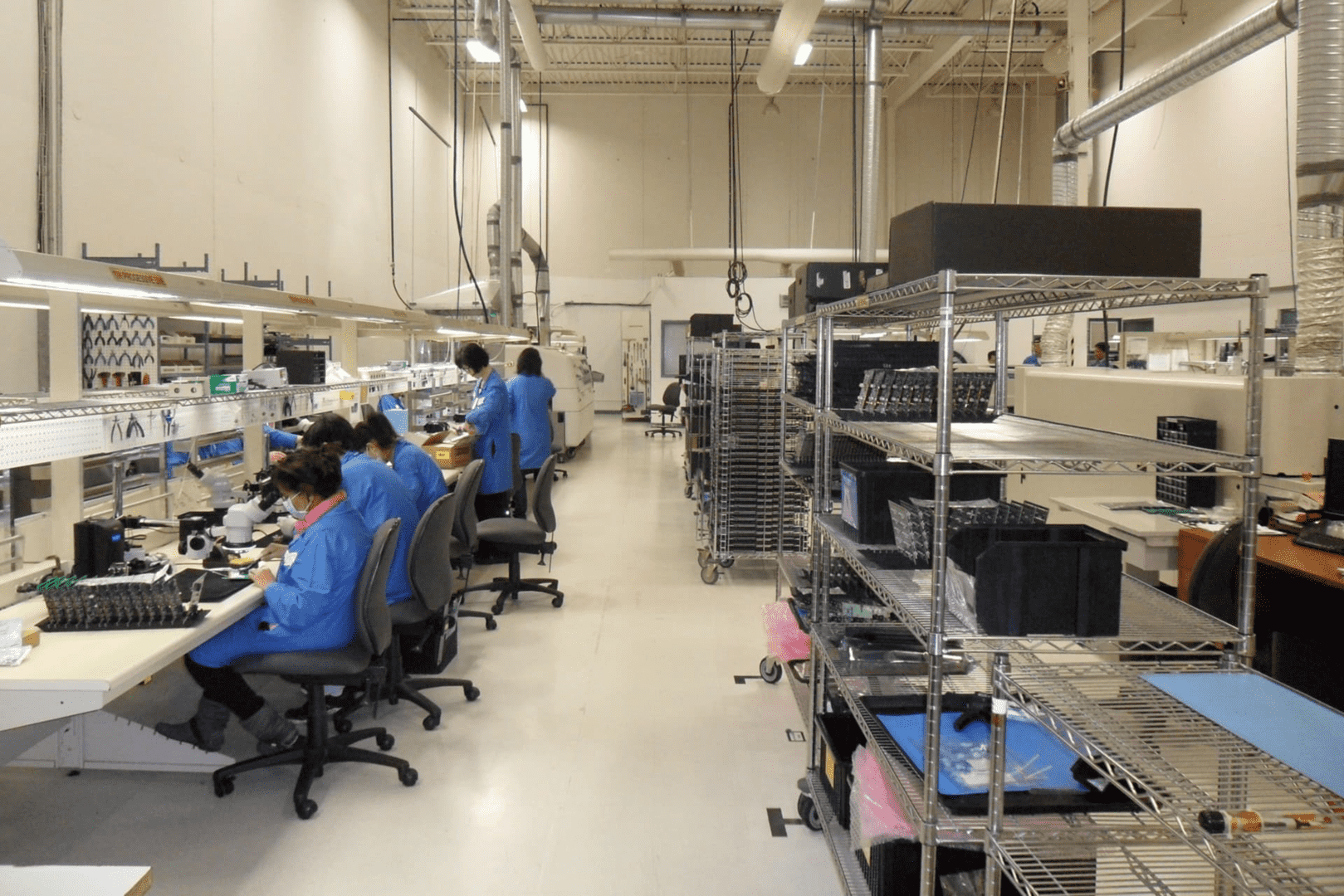
TOKO TECH is an export-driven manufacturing enterprise specializing in the R&D, production, and sales of high-end metal pipeline systems. Headquartered in Shanghai, China, with manufacturing facilities located in the Yangtze River Delta—China’s industrial core region—the company operates a modern production base.
Since its establishment, TOKO TECH has adhered to the core philosophy of "La qualité d'abord, l'innovation ensuite, dedicated to providing high-performance, corrosion-resistant, and high-temperature/high-pressure pipeline products for global clients. These products are widely used in industries such as petrochemicals, energy and power, shipbuilding, pharmaceutical and food processing, and environmental engineering.
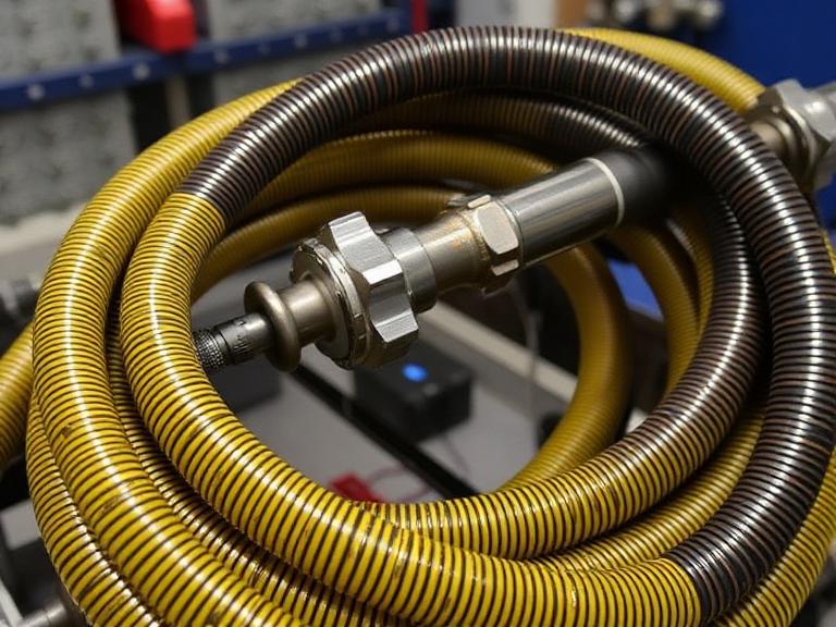
Premium Coiled Tubing Solutions:
Real-Time Fatigue Modeling
Modern control cabins utilize sophisticated software that tracks “running meters” and fatigue cycles. By creating a digital twin of the tubing string, operators can predict exactly when a section of the pipe will become unsafe. This data-driven approach allows operators to cut off fatigued sections before they enter the well, maintaining absolute structural control.
4. Downhole Reach Control: Friction and Force Management
The final aspect of control occurs miles underground. As the tubing is pushed into a horizontal well, it encounters friction against the casing wall. Eventually, the force required to push the pipe exceeds the pipe’s stiffness, causing it to buckle (first sinusoidal, then helical). Once helical buckling occurs, the pipe locks up (“lockup depth”) and can no longer be pushed, regardless of how much force the injector applies.
Extended Reach Technologies
To control this limitation and extend reach, operators utilize several technologies:
- Vibration Tools (Agitators): These fluid-driven tools create pulses that vibrate the tubing string. This vibration breaks the static friction between the tubing and the casing, allowing the pipe to slide further.
- Tapered Strings: By utilizing a tubing string with varying wall thicknesses (heavier at the top, lighter at the bottom), operators can manage the weight distribution to delay buckling.
- Friction Reducers: Chemical additives (polymers or beads) are pumped down the well to lubricate the interface between the steel surfaces.
Using these methods allows operators to control the tubing’s behavior deep in the lateral sections of the well, ensuring target depth is reached for stimulation or cleanout.
Summary Table: Control Mechanisms
Understanding the interplay between these mechanisms is vital for successful interventions. Below is a summary of how these ways to control coiled tubing interact.
| Control Method | Primary Equipment | Fonction | Risk Mitigated |
|---|---|---|---|
| Surface Mechanical | Hydraulic Injector Head | Provides push/pull force and traction. | Uncontrolled pipe movement, run-away pipe. |
| Well Pressure | Strippers & Quad-BOP | Seals wellbore fluids during motion. | Blowouts, environmental spills. |
| Integrity/Material | High-Alloy Tubing (TOKO TECH) | Resists corrosion and fatigue cycles. | Pipe rupture, parting downhole, H2S leaks. |
| Downhole Reach | Agitators & Tapered Strings | Reduces friction and buckling. | Lockup, inability to reach target depth. |
Foire aux questions (FAQ)
Références
For further reading on advanced alloy specifications and pipeline integrity, consult the technical resources provided by TOKO TECH regarding ASTM B444 and UNS N06625 standards. Understanding the metallurgical properties of these materials is essential for modern well intervention planning.
Conclusion: Mastering the ways to control coiled tubing requires a synergy of mechanical force, hydraulic barriers, material science, and downhole physics. As wells become deeper and environments more hostile, reliance on high-quality manufacturing partners like TOKO TECH and advanced control systems will only increase, ensuring safe and efficient energy production for the future.