Índice
- Why Use a Shell and Tube Heat Exchanger?
- Core Steps in Designing a Shell and Tube Heat Exchanger
- Detailed Design Procedure (Thermal & Hydraulic)
- Mechanical & Material Design Considerations
- Common Configurations & Tube Layouts
- Summary Table: Design Steps & Key Checks
- Company Spotlight: TOKO TECH — Premium Tube Supplier
- Preguntas más frecuentes (FAQ)
- References & Further Reading
Why Use a Shell and Tube Heat Exchanger?
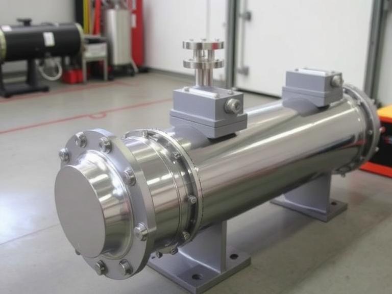
Shell and tube heat exchangers (STHE) remain one of the most widely used heat exchanger types worldwide because of their robustness, versatility and ability to handle high pressures, high temperatures, and corrosive environments. Their major advantages include:
- High pressure and temperature tolerance — ideal for industrial processes.
- Flexibility — tube materials, shell materials, pass arrangements, and tube layouts can be varied.
- Ease of manufacturing and maintenance — tube bundles can be replaced or cleaned.
- Compatibility with different fluids — from water to corrosive chemical streams.
Core Steps in Designing a Shell and Tube Heat Exchanger
The overall process for designing a shell and tube heat exchanger can be summarized in the following high‑level steps:
- Define process requirements and duty (flow rates, inlet/outlet temperatures, pressures, fluid properties).
- Select appropriate exchanger type and configuration (e.g. fixed tube sheet, U‑tube, floating head).
- Perform preliminary sizing (estimate heat transfer area, number of tubes, shell diameter, length).
- Conduct thermal and hydraulic calculations — heat transfer, LMTD, pressure drops.
- Iterate design if performance or pressure drop constraints are not met.
- Perform mechanical design: thicknesses, materials, stress checks, expansion, nozzle design.
- Prepare detailed drawings and manufacturing specifications.
Detailed Design Procedure (Thermal & Hydraulic)
Below is a more detailed breakdown of each step for engineers designing a shell and tube exchanger.
Step 1: Define Process Requirements
Start by specifying:
- Hot and cold fluid types
- Inlet and desired outlet temperatures
- Mass flow rates
- Operating pressures and maximum allowable pressure drop
- Corrosion, fouling tendencies, and fluid compatibility
Also gather thermophysical properties of both fluids (density, viscosity, specific heat, thermal conductivity) at mean or caloric temperatures.
Step 2: Heat Duty & Energy Balance
Use the energy balance to calculate the required heat duty (Q):
Q = m × cₚ × ΔT (for both hot and cold side, ensuring balance)
Step 3: Select Trial Overall Heat Transfer Coefficient (U₀ₐₛₛₘ)
Based on fluid properties and prior data, assume a reasonable overall heat transfer coefficient. This serves as the starting point for sizing.
Step 4: Select Configuration and Pass Arrangement
Decide on:
- Number of shell passes
- Number of tube passes
- Shell and tube side fluid allocation (which fluid goes inside tubes or shell).
Step 5: Estimate Geometry — Tubes, Shell, and Layout
Determine:
- Number of tubes (based on required area and tube dimensions)
- Tubing layout: triangular or square pitch — triangular increases turbulence and heat transfer, square allows easier cleaning.
- Shell diameter and length
- Baffle type, spacing and cut — to guide shell-side flow and enhance turbulence.
Step 6: Thermal & Hydraulic Performance Calculation
Compute:
- Log Mean Temperature Difference (LMTD) or use correction factor for multi-pass exchangers.
- Heat transfer area required, based on U, LMTD, and Q
- Shell-side and tube‑side pressure drops — ensure they are within allowable limits for pumping costs and mechanical design
Step 7: Mechanical Design & Material Selection
Once thermal design is satisfactory, move to mechanical and manufacturing design:
- Select tube & shell materials based on fluid compatibility (e.g. corrosion resistance, high pressure, high temperature)
- Calculate wall thickness, nozzle sizes, tube sheet strength, and expansion allowances for thermal stress — essential for safety and durability.
- Design proper tube-to-tube sheet joints (e.g. expanded, welded, seal‑weld) depending on service conditions.
Common Configurations & Tube Layouts
Engineers must choose from several standard arrangements depending on service requirements:
Fixed Tube Sheet vs Floating Head vs U‑Tube
– Hoja de tubo fijo: Simple, cost-effective — best when shell-side fluid is clean and temperature difference is small.
– Cabeza flotante: Allows for differential expansion — suited for large temperature differences or shell-side fouling fluids.
– U‑Tube: Offers thermal expansion tolerance — suitable for high-temperature, high-pressure applications.
Tube Layout: Triangular vs Square Pitch
A triangular pitch increases turbulence and heat transfer efficiency but complicates cleaning, while a square pitch is easier to clean but slightly less efficient. For fluids prone to fouling, square pitch is often preferred.
Summary Table: Design Steps & Key Checks
| Step | Main Output / Decision | Key Consideration |
|---|---|---|
| Process definition | Fluid data, flow, temperatures, pressures | Accurate thermophysical data and fluid compatibility |
| Preliminary sizing | Estimated area, shell/tube dimensions | Reasonable assumed U-value, layout feasibility |
| Thermal & hydraulic calculations | Heat duty, LMTD, pressure drops | Performance meets duty and limits |
| Mechanical design | Wall thickness, material, joints | Safety, code compliance, corrosion resistance |
| Final drawing & specs | Manufacturing-ready documentation | All design constraints satisfied |
Company Spotlight: TOKO TECH — Premium Tube & Pipe Supplier for Heat Exchangers
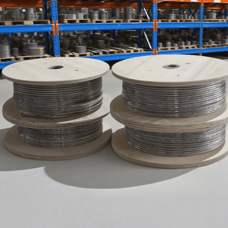
TOKO TECH is a leading manufacturer specializing in precision coiled heat exchanger tubes and high‑end metal pipeline systems. Headquartered in Shanghai, China, with advanced facilities in the Yangtze River Delta — China’s industrial core — TOKO TECH is committed to “Quality First, Innovation Driven.” Their products are widely used in petrochemical, energy & power, shipbuilding, pharmaceutical, food processing and environmental engineering sectors worldwide.
Available Products from TOKO TECH
These high-quality tubes and pipes provide the ideal foundation for durable, efficient shell and tube heat exchangers. Selecting materials from TOKO TECH ensures reliability under high temperature, high pressure, or corrosive fluid conditions — matching the stringent requirements of modern industrial applications.
Preguntas más frecuentes (FAQ)
Q1: What is the first step when designing a shell and tube heat exchanger?
The first step is to define process requirements — fluid types, flow rates, inlet/outlet temperatures and pressures, and desired performance (heat duty, pressure drop limits, material compatibility).
Q2: How do I choose between fixed tube sheet, floating head, and U‑tube designs?
Choose based on temperature difference, maintenance needs, and fluid service. Fixed tube sheet is simplest; floating head helps with thermal expansion and fouling; U‑tube handles high temperature/pressure and differential expansion well.
Q3: Why is tube layout important?
Tube layout (triangular vs square pitch) affects heat transfer efficiency, shell-side turbulence, ease of cleaning, and maintenance. Triangular pitch gives higher heat transfer, square pitch simplifies cleaning.
Q4: Can I design a shell and tube exchanger manually or should I use software?
Initial sizing and conceptual design can be manual using established methods (e.g. Kern method). However, final design and verification—especially for complex services—should use thermal and mechanical design software for accuracy and safety.
Q5: What materials are recommended for best durability?
Materials like stainless steel, nickel alloys, or other corrosion-resistant metals are often used — especially if fluids are corrosive or the service involves high pressure/temperature. Suppliers like TOKO TECH offer a wide selection of premium tubes and materials.